STUDIO 2
Building instruction
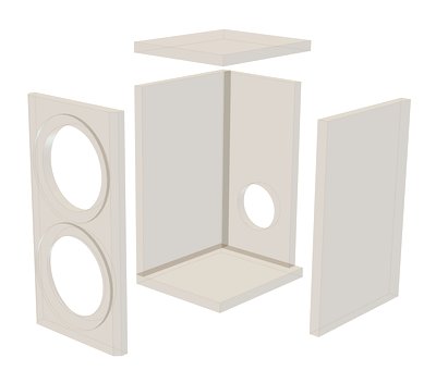
Exploded drawing
Assembly
The construction of the STUDIO 2 is very easy because all the cabinetpanels are butt-jointed and glued. Before you start, decide on what you want the speakers to look like. You could, for example make the front panel out of attractive solid wood, which gives the cabinet a sophisticated touch. The thickness of the front panel can be varied to suit taste but, for reasons of rigidity, should not be less than 15 mm.
After all the panels have been cut to size (e.g. at your local DIY store), it is best to begin with the base and then glue the side and rear panels to it one after the other. Finally, attach the lid. The cabinet (without its front panel) should be firmly held in position with sash cramps (you can prevent individual panels from sliding as you tighten the sash cramps by e.g. hammering in a few tacks or nails and nipping off the heads). While the glue is drying, you can apply a further layer of glue to the joints between the panels on the inside to ensure the final construction will be absolutely airtight.
At this stage, you can also position the crossover provisionally and drill the mounting holes for it, which will make it much easier later on to fit the crossovers because the inside space is fairly cramped. After the glue has completely dried, cut the opening for the terminals in the rear panel e.g. using a hole saw or jigsaw.
Depending on the finish you are aiming for, you can either fit the front panel and then mill the driver openings or do the woodwork to the front panel before you glue it in place on the cabinet. The two lateral 8 mm chamfers, however, should be milled as the final step using the router, so the sides of the cabinet can be used as guides for the 45° router tool with a guide ring.
After this stage, the anchor points for the drivers and terminals can be marked out and pre-drilled (2.5 mm drill).
In the next step, removes all traces of dust from the cabinet and screw the frequency crossovers that have been wired according to the wiring layout in position inside the enclosure. Next, solder the terminal connections on and screw them in place. Then the damping material is positioned as shown in the damping distribution plan, while allowing the wires for the tweeter and woofer to protrude through the openings. Depending on how neatly the woodworking has been performed, it may not be necessary to seal the driver openings. Finally, solder on the drivers and screw them in place.
Inner damping
For the inner damping, roll up a mat of polyester wool and insert it into the cabinet through the speaker openings in the front panel. When it is in place, loosen up the mat a little and distribute it inside the cabinet.