ATLAS COMPACT MK IV
Building instruction
Exploded drawing
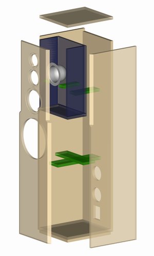
Assembly
Inside the large subwoofer cabinet there is a separate chamber that houses the low- to midrange unit. The tweeter and mid-range driver are also mounted in this cabinet. The TI 100 is separated off from this chamber by the AK 10.13 cap. The cap and connecting wires must be fitted to the rear of the baffle and well sealed (using silicon mastic or hot-melt glue) before the cabinet is glued together.
To achieve the broad bevel on the upper third of the front panel, the sides of the low- to mid-range cabinet are doubled-up. Three 8 mm holes will have to be drilled in the rear wall of the low- to mid-range chamber for the cables. These also must be well sealed off after the cables have been positioned.
The two rouond openings in the rear wall are for mounting the bass reflextubes while the rectangular one is for the terminals. The frequencycrossover unit is mounted on the wall behind the bass cut-out.
Inner damping
Two mats of damping material are pushed into the low- to medium range cabinet. A small piece of the mat (approx. 10 x 10 cm) is pushed into the cap on the mid-range driver, and the remaining 10 mats are evenly distributed around the woofer chamber.