LA BELLE CENTER
Building instruction
Exploded drawing
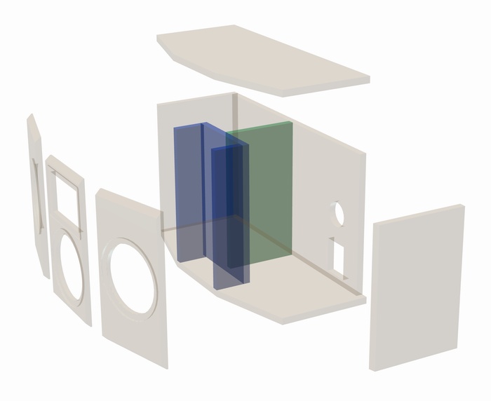
Assembly
Due to the angular front panel and the resulting interaction with other parts of the cabinet, this construction is more difficult than other instructions and will require accuracy and close attention to detail. Particular attention is required when matching the bevels on the front panels and sides and the angled cuts on the base plate and lid. We recommend doing a trial assembly run without glue. If you find during the trial run that visible joints are unavoidable, it might help to use polyurethane glue but this definitely requires you to use sash cramps while the glue dries.
First, make the cut-outs for the bass level controller and terminals and do the milling work for the recessed driver mount and waveguide. Then glue together the mid-range & high-frequency compartment including the internal baffles, i.e. all the internal panels, to create a Y-shaped construction. It is essential here to ensure that the edges are cut exactly square and the panels are of identical height. Next drill the hole for the cables. Once the glue has hardened, the rear wall, side panels and mid-range & high-frequency compartment are glued in position on the base and finally the lid glued in place. In so doing, ensure the front edges of the side panels and of the mid-range & high-frequency compartment are exactly flush with the front edges of the base and lid. The crossovers are now screwed in place in the cabinets as follows: the bass crossover is placed in the same half of the cabinet in which the terminal and bass controller are located, while the mid-range/tweeter crossover is fitted in the other half.
Now the front panels are glued in place. Make sure the front panels do not slip on the fresh glue as a result of the force of gravity. This can be prevented if you use a strap to hold them in place, but do not tighten it too much.
In the final stage, the damping material is distributed in the cabinet as described, the KE 25 SC - 8 Ohm screwed to the waveguide and this assembly and the remaining chassis fitted inside the cabinet after the soldering has been completed. The LC 95 output control is soldered in place between the KN coil (15 mH) and the 330 µF capacitor. To this end, terminal tags 1 and 2 on the bass regulator are used, as shown in the crossover drawing. To prevent blur in the waveguide we recommend sealing the mating surface with sealing tape or removable glue.
Inner damping
Four mats of damping material are uniformly distributed in each woofer chamber. Two mats are pushed into the mid-range loudspeaker chamber, one of them must be tightly rolled and positioned in the middle between the mid-range loudspeaker and tweeter. The second of these can be halved and the two halves arranged loosely around the mid-range driver and the tweeter.