NIMROD
Building instruction
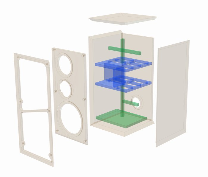
Exploded drawing cabinet
Exploded drawing stand
Building instructions
The present design of the NIMROD could not by any means be termed a beginner's cabinet and requires very precise work. It is the mitre-cut walls and the filigree grille frame that make it a particularly demanding project.
In addition, the cabinets have to be built as symmetrical mirror images of each other, which must be taken into account, especially when it comes to the front baffle and the frame, but also during the assembly process as a whole.
As with all kits, it is imperative right from the start to bear in mind the subsequent appearance. If, for example, you intend to veneer the outside surfaces at the end, the additional material thickness will have to be taken into account when routing the loudspeaker openings.
Initially, all the panels are individually prepared – drawings of the individual panels can be found in the manual to simplify the process and assist in error prevention. In this way, it is only necessary to cut the panels one at a time to the dimensions given and then assemble them later.
Since the lid, bottom and both sides are mitred and there are several chamfers, a very accurate circular table saw is advantageous. The 45° chamfers required are shown accordingly in the respective drawings.
In addition to the exact external dimensions, the following points are crucial with respect to the corresponding individual panels:
Front panel:
- At the bottom end, the transition to the bass reflex tube must be rounded off (r = 15 mm).
- The rear of the cut-out for the B 100 loudspeaker must be chamfered, otherwise the rear openings in the loudspeaker basket will be covered too much by the front baffle. A 45° chamfer with a depth of approx. 8 mm is sufficient. In order to make sure there is enough material for the speaker to be firmly mounted we recommend you do not apply chamfers at the four screw positions.
- The grille frame is fixed to the cabinet using wooden frame dowels later. As these are very close to the edge of the front panel, it is advisable to predrill them only with a small drill bit to obtain the exact position and finish them to the right size after assembly. To ensure that the frame fits exactly later, it is essential that the holes for the frame dowels are positioned very accurately.
Bass reflex panel:
- The bass reflex panel is rounded off on one side, which improves the flow characteristics and prevents audible interference.
Bracing boards:
- The two bracing boards each have five cut-outs. It is advisable to mark the openings accordingly with a pencil and then cut them out.
Grille frame:
- The grille frame is a very filigree structure. It is therefore best to start with the four outer 45° chamfers.
- Then place the front baffle centrally on the frame and copy the holes for the frame dowels, which can be drilled to the correct size subsequently.
- Finally, cut out the two inner sections, while being extremely careful especially in the lower section and around the centre strut, as these are very thin and can break easily.
- The two cut-away sections can now be used to make the four 20 mm wide bracing struts.
Now that the individual panels have been cut to size and prepared, we can do a dry run to check fitting. The panels should be fitted together as tightly as possible. It is also possible to fix the four outer panels (bottom, lid and side walls) with simple adhesive tape that is easy to remove. If all the panels fit together well, the crossover unit should be positioned in the lower part of the cabinet (the wires leading to the terminal should face downwards). To this end, the bracing on one side wall has been omitted. The mounting position can be marked here, which will facilitate subsequent installation of the crossover (align the crossover so that the supply wires to the terminal are facing down).
After this dry assembly stage, the panels can be taken apart again and the mounting holes of the crossover unit predrilled (2.5 mm drill). Note: only pre-drill the holes, they must not go right through.
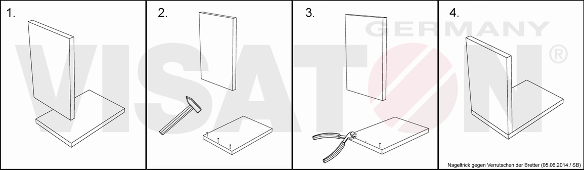
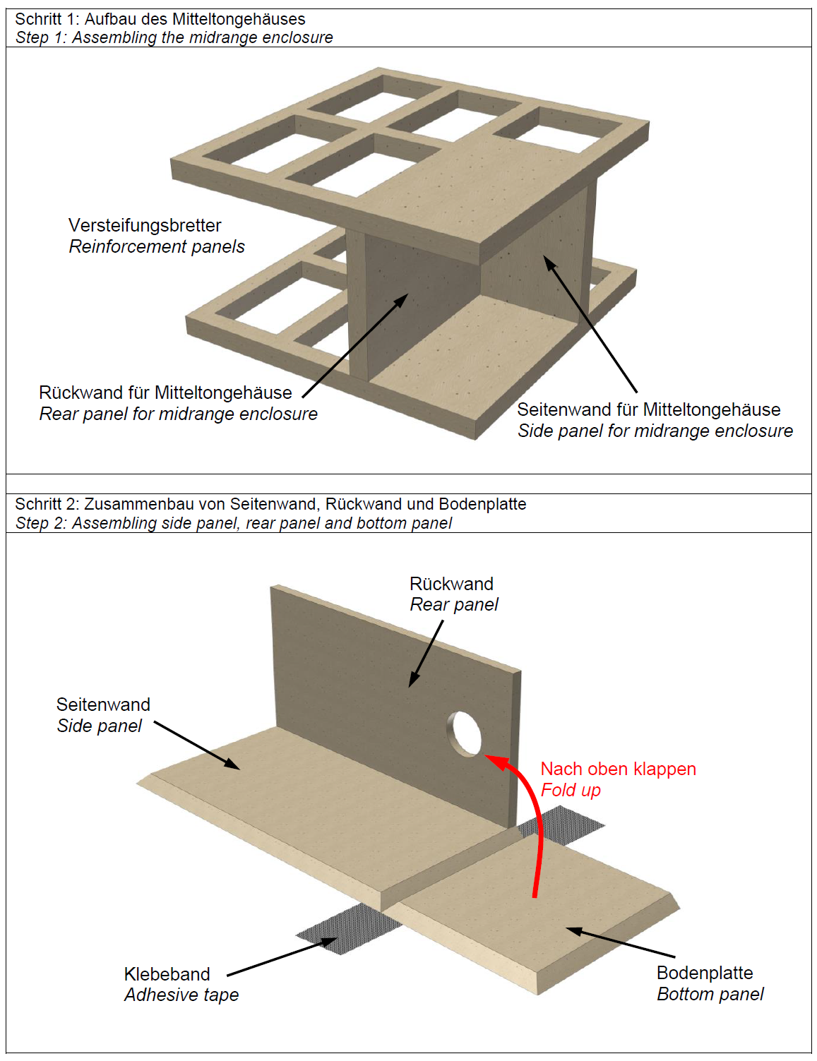
Now we can begin final assembly. It is best to start with the two bracing boards (with the five cut-outs) and the partitions for the mid-range enclosure, as these are simply butt-glued together (see Step 1 in the assembly illustrations). It is possible to prevent the panels slipping out of position by applying the “nail trick". This involves hammering thin tacks into the panels and then cutting off the heads with robust side cutters (see the explanation on this). Use sash cramps to keep the assembly in shape while it dries.
As with all butt joints, it is crucial that the panels are perfectly perpendicular to each other – use a 90° engineer's square to ensure this is the case.
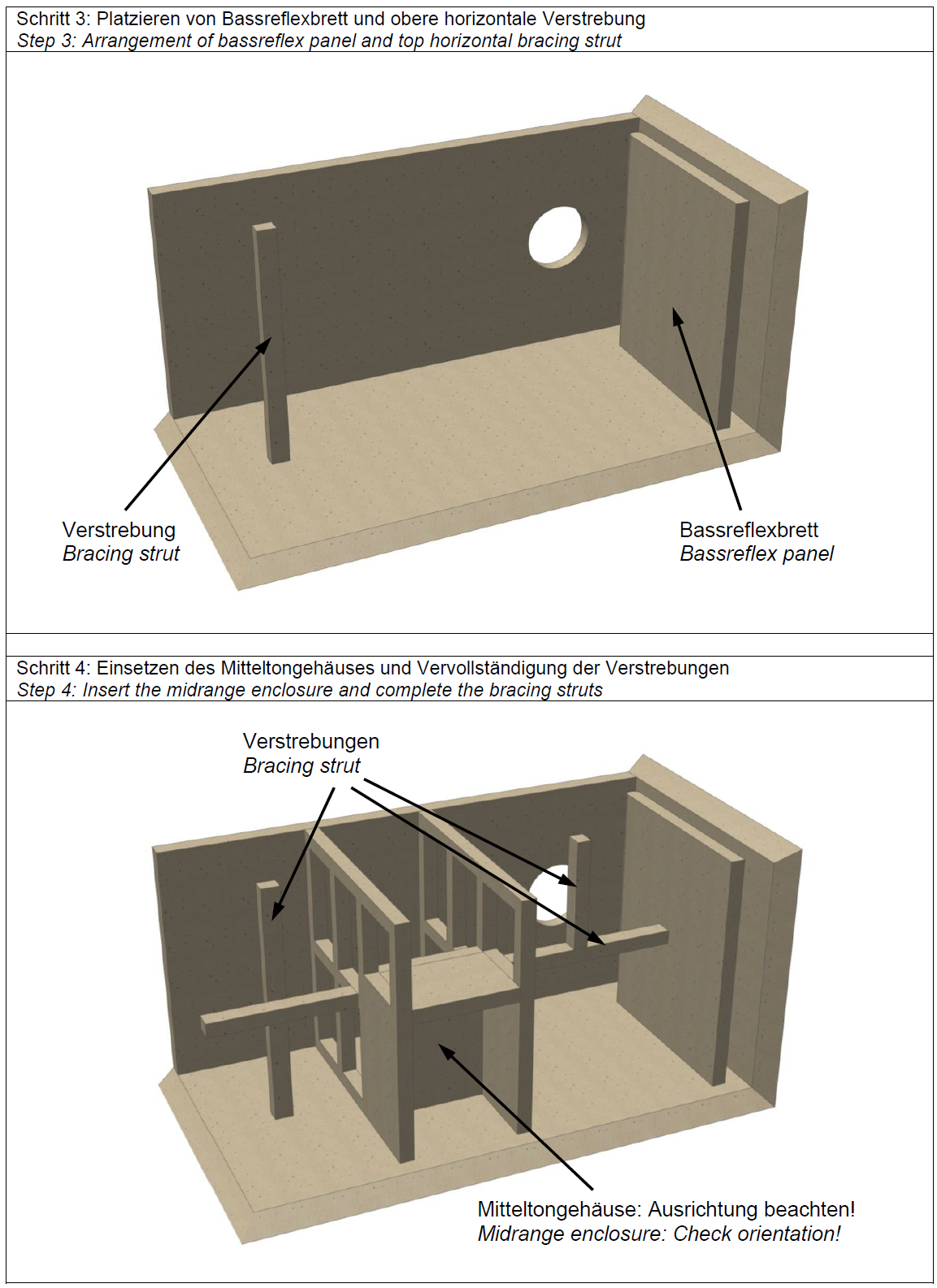
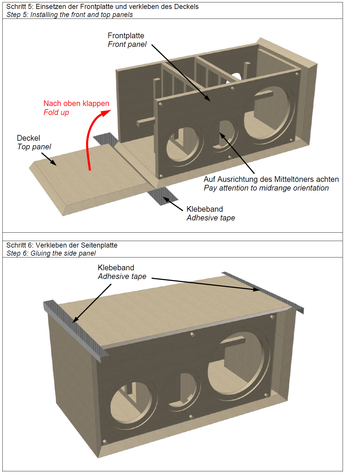
In the meantime, you can continue by gluing the back wall to a side wall and the base. To make things easier, place a strip of adhesive tape on the table (adhesive side up, length slightly more than the width of the cabinet) and position the side panel on it so that the edge that will mate with the base covers half of the width of the adhesive tape. Then place the base directly opposite it flat on the adhesive tape, which will later serve as a temporary hinge. The next step is to apply a bead of glue on both sides of the back panel and glue it to the side panel. Then apply glue to the mitre edges of the side panel and base and fold up the base so that it connects to the rear panel (see Step 2 in the assembly illustrations). Next, attach the upper horizontal bracing strut and the bass reflex board (see Step 3 in the assembly illustrations).
After this step, the assembly consisting of the bracing boards and mid-range enclosure will have dried sufficiently to be glued to the side and rear panels. It is important that the mid-range enclosure is aligned with the opening in the front baffle (remember that the left speaker is symmetrical to but a mirror image of the right speaker). Next, fit the remaining bracing struts and the front baffle (see Step 4 in the assembly illustrations).
Finally glue the lid in place. In order to ensure a clean finish on the mitred edges, it makes sense to apply a temporary hinge again using adhesive tape (see Step 5 in the assembly illustrations). Afterwards you can apply a bead of glue to all the inner edges again and smooth it using your finger.
After allowing sufficient time for thorough drying, you can remove the temporary adhesive tapes and other aids (e.g. sash cramps) and you can continue by drilling the holes for the dowels. After that, a hole is drilled for the feed wire to the mid-range loudspeaker driver. To do so, drill a 6-8 mm hole through the cut-out for the speaker into the partition wall. In the final phase of cabinet construction, all we need to do now is pre-drill the fixing points for the loudspeaker drivers, the waveguide and the terminal with a 2.5 mm drill. The actual cabinet is now ready for the final embellishments.
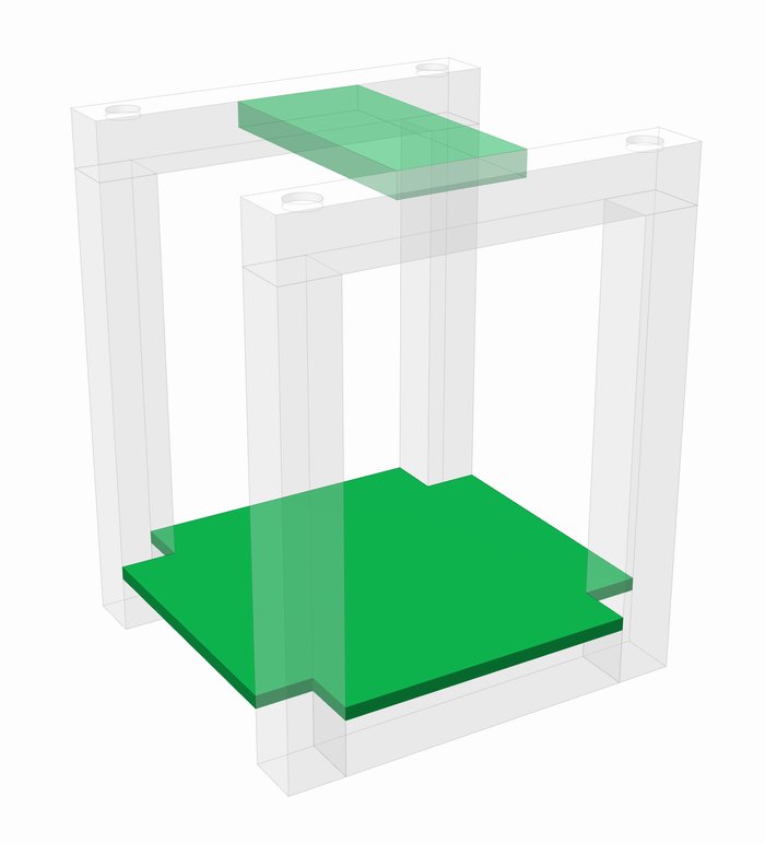
The time during the drying phases can be used for the construction of the stand. The stands consist of 8 square timbers each (44 x 44 mm), which can be cut to the right length in the DIY store. They are simply glued together as butt joints. If you have access to a dowel jointer, the square timbers can also be connected with dowels. The two intermediate boards are cut out as shown in the drawing and glued to the square timbers. Finally, drill four mounts for the cabinet feet in the upper square timbers using a pattern maker's bit.
The cabinet feet themselves can be made using a hole saw, for example. They are later attached (screwed or glued) to the loudspeaker cabinet at the appropriate places and will provide more stable positioning on the stand.
After the cabinet and the stand have been given their final finish, cleaned from dust and the grille frame has been painted, the fabric material can be applied. There are a number of ways to do this and we will now demonstrate two.
1) Hot-melt glue and an old iron:
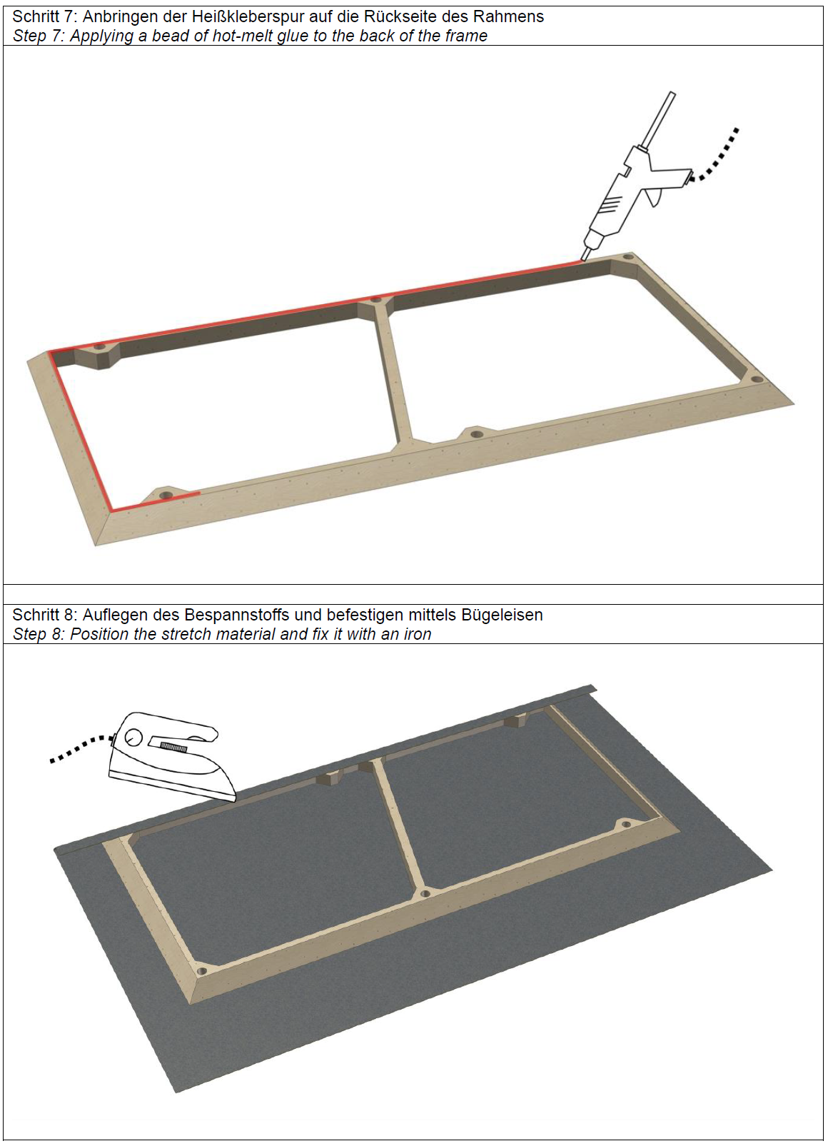
This is our preferred method because it is easy to implement and produces clean results. First of all, place the frame in front of you on a table with the rear facing upwards. Now apply a bead of hot-melt glue all along the back (see Step 7 in the assembly illustrations). After it has hardened, place the front side of the frame on the covering fabric and lift one side of the fabric over the frame (e.g. one of the long sides). Now apply the hot iron (the "cotton" setting is hot enough) and run it over the fabric under which the hot glue was applied (see Step 8 in the assembly illustrations). The hot melt glue will melt and bond with the fibres of the fabric. If the iron is too hot, place a piece of paper between the iron and the fabric. As soon as one side of the fabric is firmly attached to the frame, pull the fabric tightly to the other parallel side and fix it there in the same way. Then repeat the procedure for the other two sides. Finally, and if necessary during the work steps, the excess material is cut off with scissors or a sharp knife.
2) Staple gun:
The fabric can also be firmly attached to the back of the frame using a staple gun. However, it is very important to work very carefully here, as otherwise the staple gun can destroy the filigree frame.
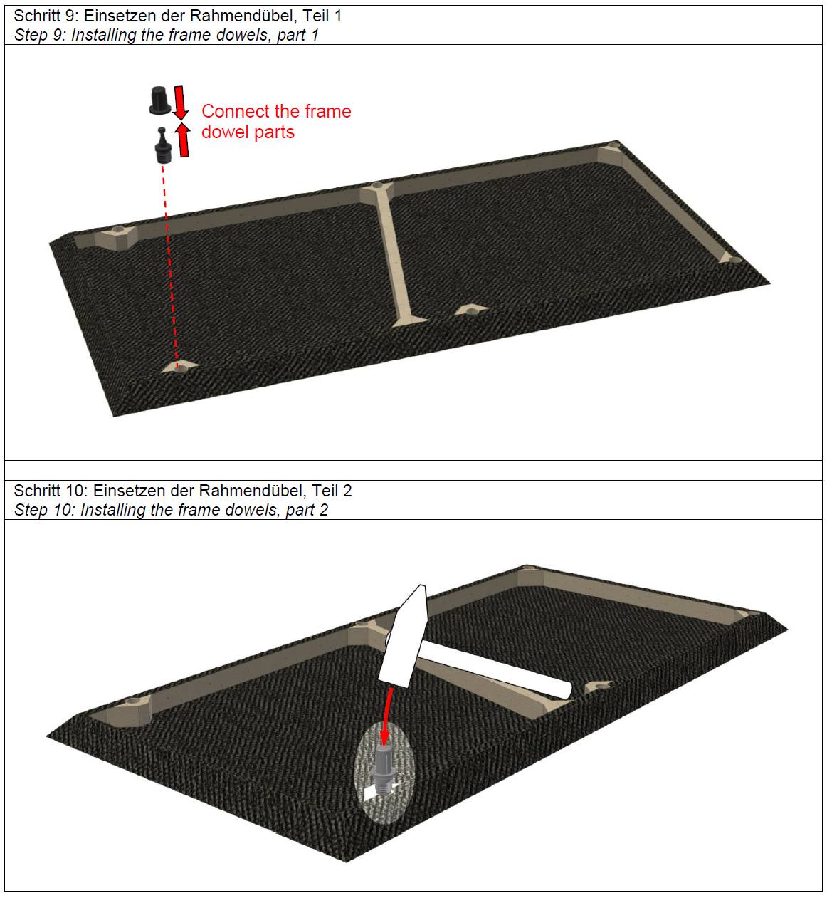
Now the dowels can be fixed in the frame and the front baffle. If the holes have been drilled very accurately, the dowels will not have to be glued afterwards. To tap the pins into the frame with a hammer, put a dowel sleeve over them first to prevent the pin breaking off (see Steps 9 and 10 in the assembly illustrations).
To complete the assembly process, we will now fit the technical items, beginning with the crossover. This item has to be prepared according to the attached connection diagram and fitted with wires. It can then be attached to the marked and pre-drilled location on the side wall of the cabinet (with the leads to the terminal pointing downwards). The wires to the respective openings in the front wall are now laid loosely so that they protrude approx. 10 cm from the cabinet. The next step is to seal off the cable lead-through in the mid-range enclosure with hot-melt glue.
Next, the cabinet is damped on the inside as shown in the diagram.
Finally, the speaker wires can be soldered in place and the speakers screwed to the housing. In this respect, please note the following points:
If the milled cut-outs in the front wall are clean and the surfaces do not show any wavy edges, no sealing tape will be required between the speakers and the cabinet. If there are wavy edges, thin window sealing tape from the DIY store can be used.
Screws have been included with the waveguide WG 148 R for attaching it to the G 25 FFL tweeter. The foam used as protection in the G 25 FFL packaging can be used as a seal between the waveguide and the tweeter.
Nail trick to prevent the boards from slipping:
Inner damping
To ensure even damping, ¼ of a mat is cut with scissors and loosely placed in the mid-range enclosure. The remaining 3 ¾ mats are inserted into the cabinet through the woofer and tweeter cut-outs and distributed loosely but evenly. It is important that the mats do not clog the bass reflex port and that they are really loose inside the cabinet. Damping on the walls is wrong and reduces the effect.
Cabinet parts list for 1 box
Note: all dimensions are gross external dimensions. Bevels and mitres are cut from these.
*) the struts can be made from the cutout sections of the grille frame