TRINITI
Building instruction
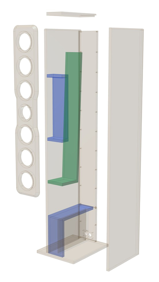
exploded drawing
Assembly
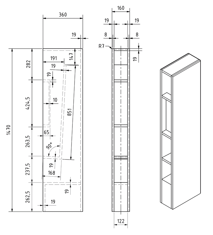
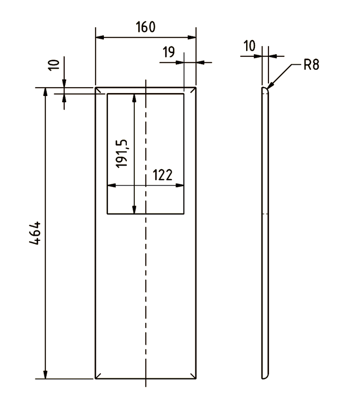
First glue the L-shaped divider sections at right angles (168 x 122 mm and 832 x 122 mm), glue the dividers of the mid-range enclosure (55 x
122 mm) to the corresponding 10 mm rear panel (425 x 122 mm), the floor (322 x 122 mm) and the front section of the base (263 x 122 mm).
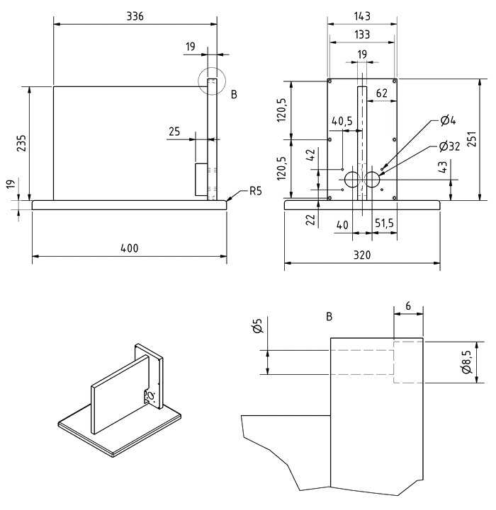
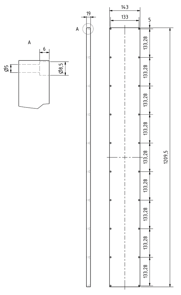
The base and PCB holder can be completely glued together.
Drill a hole in the rear wall of the mid-range enclosure big enough for two double-strand cables. With the speaker standing upright, this hole should be near the dividers of the mid-range enclosure. When selecting the hole position, be sure to consider the installation depth of the mid-range drivers. Then drill a hole in the shorter part of the L-shaped divider for three wires and in the middle of the base.
Glue the mid-range enclosure, the L-shaped divider, base, front base section and cover to the side panels. With the mid-range enclosure, cover and L-shaped divider, it is essential to ensure that they are exactly flush with the front so that the front panel can later be mounted flush and airtight on all sides. When attaching the base and front base section, ensure the glued parts are flush with the rear rebate.
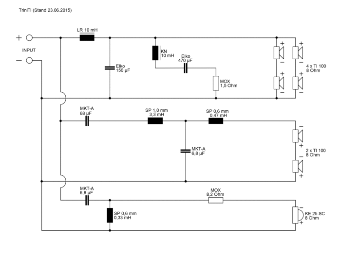
Now pass the cables for the mid-range drivers and the tweeter through the hole in the mid-range enclosure and the cables for all three sections through the L-shaped divider and the base. Note here that the mid-range drivers must be connected in series and the woofers in parallel or in series. The holes must be well sealed afterwards.
Hot-melt glue is recommended for this task.
Now cover the fabric frame with the fabric and attach the front. You can use such solutions as tongue and groove or dowels or it can be glued over the entire surface. What is crucial is that all the surfaces are fully airtight.
The inner damping is now inserted into the cabinet in accordance with the following instructions.
Now glue the sealing tape into the rebate or onto the back wall.
Solder the chassis, crossovers and terminal and screw them firmly in place. Position the low-frequency crossover with the LR coil as close as possible to the terminal on the right side of the base (viewed from the front). Fasten the mid-range/tweeter PCB with the large SP coil close to the base and as far towards the front as possible. Now screw the fabric frame to the front of the base from the inside. Finally, screw the terminal, base and rear panel together.
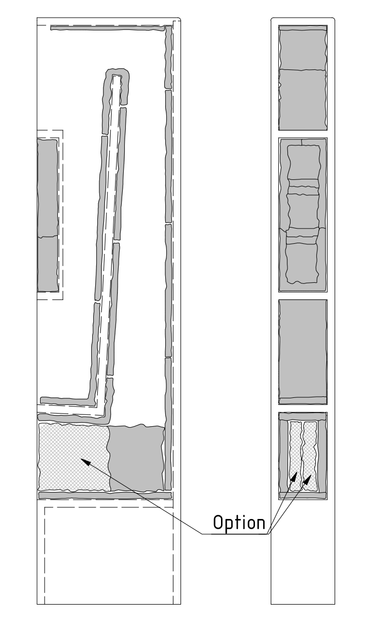
Inner damping
Horn damping
In contrast to most other kits, which also allow for larger deviations from the damping arrangement, this kit requires very close adherence to the prescribed damping layout. This is why the back has been designed to be removable.
Using scissors, cut two mats of damping material into 5 equal strips of 12 x 33 cm each, and from the third mat cut three more strips of 12 x 33 cm each and three strips of 5.5 x 33 cm each. The fourth mat will be cut to size later. We recommend fixing each strip at the ends and, if necessary, in the middle, with a manual staple gun. No additional fixing is necessary. Due to the very cramped conditions inside the cabinet, using a staple gun is often difficult, so attaching with double-sided adhesive tape, spray-on adhesives, nails, etc. may be suitable alternatives. However, it must be ensured that the mats will never be able to slip. The use of other damping wool is also very
critical and is therefore not recommended. The strips of damping do not have to be stretched, compressed or shaped, they are simply loosely positioned and fixed in place.
Line the back wall over the entire length with the damping strips (approx. 3.5 strips). When fitting the
rear panel, make sure that no damping material gets into the rebate, and if necessary cut the strips a little narrower. The same applies when determining the length. Now line the bottom of the horn opening with a strip. Also completely line the L-shaped divider with six strips. It is best to start at the horn opening and place one strip after the other end-to-end. If the last strip is too long, it can be shortened to the appropriate length. The cavity behind the mid-range/tweeter enclosure is very difficult to line, but it must be ensured that the strips cannot slip. It is also possible to connect two strips to form one long strip using an office stapler or by sewing them together. Attach another strip to the lid of the cabinet. This piece must be fixed in the centre (exactly vertically above the divider) in such a way that this strip can never slip, which would block off the tube. Now line the bottom of the horn opening with another strip.
Cut one mat into three strips of approx. 17 x 33 cm. Two strips will cover the sides of the horn opening. The remaining strip can be halved and inserted into the horn opening as an option.
Inner damping for the mid-range section
Fully line the rear wall of the enclosure with a strip and the remainder of the mat used on the removable rear panel. Any overhanging insulation material can be cut off. Now line the side walls of the mid-range enclosure with the three 5.5 x 12 cm strips. Gentle stuffing is recommended. Cut four pieces of approx. 6 x 6 cm from the remaining strip of damping material and fill the hollow area between the tweeter and the openings for the mid-range drivers with two pieces each. When the mid-range drivers are positioned, they will now be completely surrounded by damping material. If any damping material is left over, an additional layer can be added behind the tweeter.
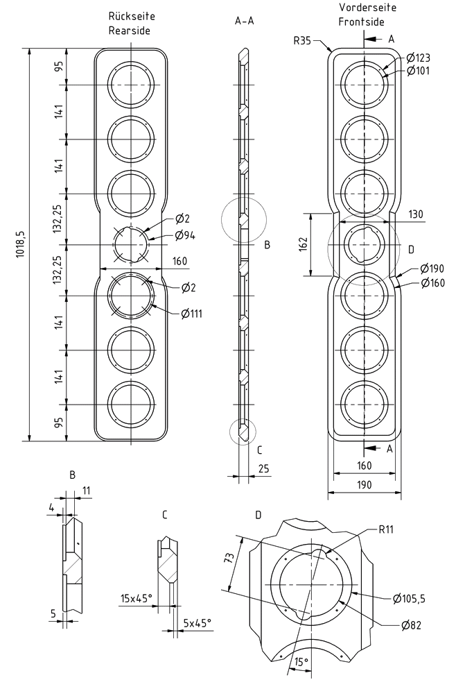
Cabinet parts list for 1 box
Suggested accessories:
Sealing tape (thin with good compressibility)